Service: Spring Probes Pogo Pins
Spring probe and pogo pin support for compact repeat-mate interconnects
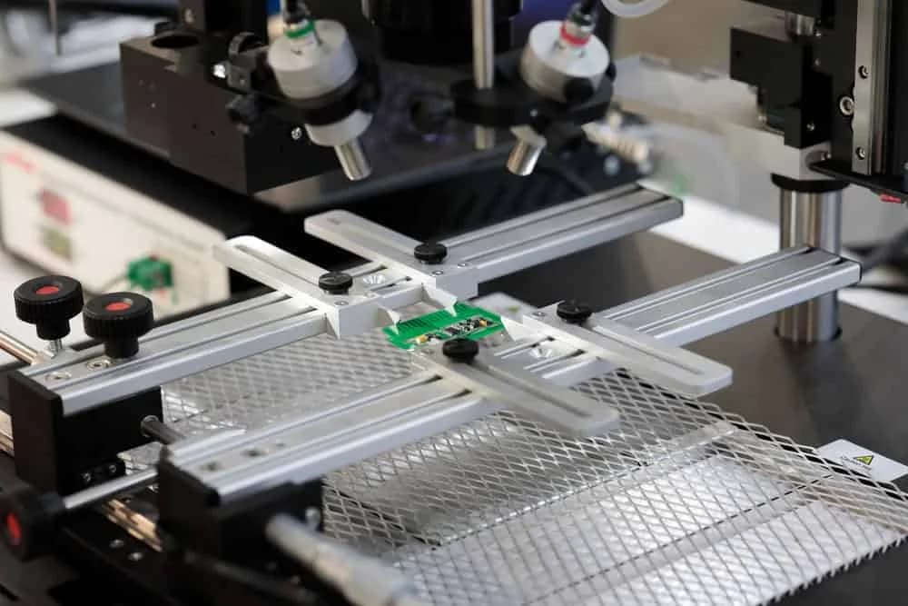
Pogo pin programs succeed when contact force, stroke window, plating, pad finish, and mechanical retention are reviewed as one assembly problem. We help OEM teams move charging docks, fixture contacts, programming cradles, and compact accessory interfaces into controlled low-volume production.
What buyers should watch on spring probes pogo pins
For useful background, see pogo pins, bed-of-nails testers, and electrical connectors. In production, a spring contact is not just a catalog part. It sits inside a force window, a wear mechanism, and a real tolerance stack that has to survive repeated mating.
That makes pogo pin integration a real manufacturing service. Many buyers already know they want a compact repeat-mate contact, but still need help deciding whether the chosen pin, pad finish, receptacle, housing, and inspection plan can make it through a pilot build without unstable contact performance.
Contact Force Has To Match the Real Stroke Window
A pogo pin that looks acceptable in a nominal CAD position can fail quickly if the actual assembly tolerance leaves too little or too much compression.
Pad Finish and Plating Decide Long-Term Stability
Contact reliability depends on more than the spring pin itself. Gold thickness, base material, surface finish on the mating pad, contamination exposure.
Mechanical Retention Often Creates the Real Production Risk
Compact charging docks, battery contacts, and fixture blocks can fail because the pin barrel, insulator, or carrier plate is not properly supported.
Contact integration scope
| Typical scope | Spring probes pogo pins for charging docks, battery contacts, programming cradles, test fixtures, modular accessories, and compact board-to-board interfaces |
|---|---|
| Contact configurations | Single contacts, multi-pin arrays, mixed power and signal layouts, receptacle-based assemblies, and housing-integrated contact modules |
| Engineering review | Stroke window checks, contact-force review, pad-finish coordination, tolerance-stack analysis, housing fit validation, and serviceability planning |
| Manufacturing controls | Part-number alignment, insertion or retention method review, assembly fixturing, electrical inspection points, and serialized low-volume release records |
| Related manufacturing | PCB assembly, fixture build, connector integration, cable assembly, wire harness support, electromechanical assembly, and box build |
| Best fit | Prototype, pilot, bridge, and controlled low-volume programs where blind-mate reliability and cycle-life risk need early review |
Design details that usually decide the outcome
Working Stroke and Overtravel Control
The contact should operate in its intended compression range in the real assembly, not only in the nominal stackup. Hard stops, enclosure flex.
Tip Geometry and Pad Interaction
Crown, dome, concave, or spear-style tips behave differently on flat pads, mating domes, battery terminals.
Current Density and Thermal Rise
Power pogo pins used for charging or battery discharge should be checked for contact resistance, current sharing.
Retention and Field Replacement Strategy
Pins pressed into a fixture plate or plastic carrier need a retention method that survives handling, cleaning.

How we move a pogo pin program into production
1
Use-Case and Contact Review
We start with the real use case: charging, signal transfer, fixture testing, battery connection, or modular docking. That clarifies current per contact.
2
Mechanical Envelope and Landing Validation
The contact array, pad layout, carrier plate, receptacle, and support structure are reviewed together. This is where stroke margin, pitch clearance.
3
Assembly and Inspection Definition
We define whether pins are pressed, soldered, screwed into a holder, or assembled into a submodule. Work instructions, handling rules, force limits.
4
Pilot Build and Controlled Repeat Supply
Pilot observations are converted into released documentation covering contact part numbers, acceptable compression range, electrical checks, fixture notes.
Common applications
Charging Docks and Battery Interfaces
Products that need compact charging contacts, blind-mate tolerance, and repeatable insertion across frequent user cycles without a fragile plug-in connector.
Programming and Service Cradles
Electronics that use temporary contacts for firmware loading, calibration, diagnostics.
Bed-of-Nails Test Fixtures
Fixture programs that depend on stable contact resistance, correct probe selection, and manageable maintenance intervals across repeated PCB test cycles.
Modular Medical and Industrial Devices
Docking or accessory interfaces where compact sealed packaging, wipe action, and controlled contact wear matter more than a conventional exposed connector.
Where this service fits in a larger build
Pogo pins are often treated as a small line item even when they decide whether a dock, fixture, or field-service interface works reliably. Programs move faster when contact selection is reviewed together with the PCB, housing, cable exits, battery geometry, and production inspection plan.
That is especially true when the same supplier is already supporting PCB assembly, harness integration, test fixtures, or final box build. The contact system should not be the last unmanaged interface in an otherwise controlled release.

Related services and references
ICT Testing Service
Useful when pogo pins are part of a bed-of-nails fixture strategy and the buyer also needs fixture planning, test coverage definition.
Obsolete Connector Replacement
Relevant when a pogo contact system is replacing a discontinued connector or when a service part needs a mechanically compatible contact solution.
Custom PCB Assembly
Helpful when the pogo-pin interface sits inside a broader board-level assembly with programmed parts, mixed sourcing, or release-controlled build variants.
RF Cable Assemblies
Useful when the project combines spring contacts with shielded cable or dock-side interconnect hardware in the same electromechanical build.
REACH Compliance for Electronics Manufacturing
Useful background when material declarations and plating-related compliance records matter on contact components and finished assemblies.
Electronics Glossary
Helpful when teams need a shared language for contact force, plating, tolerance stack, and other interconnect terms during sourcing review.
Frequently asked questions about spring probes pogo pins
What does a spring probes pogo pins service usually include?
It usually includes contact-pin family review, stroke and force matching, pad and landing-zone checks, plating and wear considerations, fixture or housing fit review, assembly planning, and low-volume production support for the finished interconnect module.
Are pogo pins only used for test fixtures?
No. Pogo pins are common in bed-of-nails test fixtures, but they are also used in charging docks, battery interfaces, programming cradles, modular accessories, medical docking systems, and compact service connectors where repeated blind mating is expected.
What usually causes pogo pin failures in production?
The most common issues are incorrect working stroke, poor plating choice, contamination at the mating pad, weak mechanical support, tolerance stack problems in the housing, and unrealistic cycle-life assumptions for the real user environment.
What should buyers send for a quote?
The best package includes target current per contact, signal type, mating-cycle expectation, pitch, available stroke, mechanical envelope, pad finish, board or harness interface details, and any fixture, charging, or environmental requirements.
Can spring probes be combined with PCB assembly and cable or harness work?
Yes. Many programs need pogo pins integrated into a PCB, dock, or electromechanical subassembly together with cable terminations, connector hardware, molded parts, or a final enclosure. Those dependencies should be reviewed together instead of as separate purchases.
Do all pogo pin programs need custom parts?
No. Some applications work with standard probe bodies and receptacles, while others need custom barrel length, spring force, plating, tip geometry, or retention features. The right choice depends on the duty cycle, current load, and mechanical packaging.
Need a pogo pin design or sourcing review?
Send the contact part numbers, stroke target, pad details, housing constraints, and expected cycle count. Early review is cheaper than debugging unstable contact behavior after tooling or pilot hardware is already committed.

Backed by our Shenzhen SMT factory
26 placement machines · 11 SMT lines
4 nitrogen reflow ovens
100% 3D SPI & AOI inspection
Per-board MES traceability
01005 & PoP in stable production