Fixture, firmware, and release evidence
PCBA Functional Testing Service for Boards That Must Ship With Proof
YourPCB supports functional test planning for PCB assemblies that need more than visual inspection: firmware loading, powered checks, test fixtures, pass/fail records, and release decisions that hold up during pilot and low-volume production.

TL;DR
- Functional testing proves PCBA behavior after assembly, programming, and powered checks.
- ICT and flying probe catch assembly faults; functional test confirms product behavior.
- Fixture cost depends on access points, firmware, loads, software, and record needs.
- Release records should name fixture revision, firmware revision, limits, and pass/fail status.
What This Service Covers
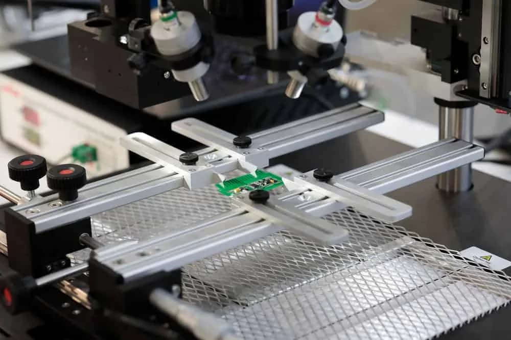
PCBA functional testing is a powered verification process for an assembled circuit board. A test fixture is a controlled interface that contacts pads, connectors, or headers so the board can be stimulated and measured consistently. A release record is a traceable factory output that links the tested board or lot to the approved firmware, fixture, limits, operator, and date.
This page fills the gap between ICT testing, flying probe testing, and full box build assembly. ICT and flying probe are excellent for assembly defects, but many OEM buyers also need proof that firmware loads, current draw is sane, communication ports respond, outputs switch, and the board can move into cable integration or final enclosure work.
Standards give the discussion a common language. IPC electronics standards provide context for IPC-A-610 assembled-board acceptability and IPC-J-STD-001 soldered assembly process expectations. ISO 9000 quality management explains why test records, revision control, and nonconforming output handling matter when boards ship in repeat lots.
Functional Test Capabilities
Test Strategy Review
We separate inspection coverage, ICT or flying probe coverage, programming steps, powered functional checks.
Firmware and Programming Control
Firmware file names, checksum expectations, programming headers, bootloader behavior, and label requirements are tied to the build revision.
Fixture and Adapter Planning
Pogo-pin access, mating connectors, edge contacts, load boards, cabling, clamps, and operator prompts are reviewed against board layout and quantity.
Power and Communication Checks
Input current, rail voltage, sensor simulation, CAN, UART, USB, Ethernet, relay, LED, and other product-specific behaviors can be captured in a pass/fail flow.
Lot-Level Release Records
The test route can produce lot status, serial status, failure disposition, rework notes, and shipment holds when a result does not match the approved limit.
PCBA-to-System Handoff
Functional test decisions are aligned with cable integration, enclosure assembly, and box build work so later system tests do not hide board-level problems.
Capability Table
| Best-fit stage | Prototype validation, pilot builds, bridge production, low-volume OEM supply, and repeat PCBA programs |
|---|---|
| Typical inputs | Schematic, BOM, Gerber or ODB++, XY data, firmware, limits, connector map, power range, communication notes, and golden-unit behavior |
| Fixture options | Pogo-pin beds, mating harnesses, connector adapters, load boards, manual prompts, barcode or serial capture, and PC-controlled sequences |
| Common checks | Power-up current, voltage rails, firmware programming, communication ports, sensor inputs, outputs, LEDs, relays, and customer-defined functions |
| Companion methods | AOI, X-ray, ICT, flying probe, continuity, programming verification, visual inspection, and final box-build test |
| Record outputs | Pass/fail status, serial number, firmware revision, fixture revision, operator, date, failure code, and shipment disposition when required |
| Standards context | IPC-A-610 acceptability, IPC-J-STD-001 soldering process logic, ISO 9001 record control, and customer-specific test limits |
Which Test Path Fits the Build?
Functional test should not be specified as a vague final check. The right route depends on what can fail, how expensive rework is, and whether the product will move into cables, enclosure assembly, or customer installation after the PCBA ships.
| Buyer situation | Best-fit path | Why it matters |
|---|---|---|
| Prototype board with no stable firmware | Inspection plus basic power-up checks | The buyer needs early assembly feedback without spending fixture budget before the test method is stable. |
| Low-volume control board with connectors | Functional test with mating adapter | Connector pinout, rail behavior, and signal response need confirmation after soldering and programming. |
| Dense SMT board with hidden joints | AOI, X-ray, then functional test | Workmanship risk and powered behavior are different failure modes and should not be treated as one test. |
| Board shipped into a box build | Board-level test before enclosure integration | Catching the board failure before cabling and enclosure work prevents expensive disassembly and unclear root cause. |
| Repeat program with split deliveries | Serial or lot-level release logging | The buyer needs delivery visibility and exception records across multiple POs or shipment dates. |
Functional Test Workflow
1
RFQ and Test Boundary
We review the board files, firmware status, product function, access points, quantity, and risk level to decide what the functional test must prove.
2
Fixture and Limits Plan
Engineering defines how the board will be powered, programmed, contacted, stimulated, measured, logged, and held if a result falls outside the approved range.
3
First Article Correlation
Early samples are checked against golden-unit behavior, debug notes, inspection findings, and buyer feedback before the release method is used on the lot.
4
Production Test Execution
Operators follow the released route, capture pass/fail status, separate suspect boards, and keep rework or retest decisions visible to the program owner.
5
Shipment Release
The lot is released with the agreed record level, packaging notes, firmware revision, exceptions, and any open engineering actions needed for the next build.

Buyer Evidence to Lock Before Production
The strongest RFQ packages define both the test and the evidence. Name the firmware revision, expected checksum, input voltage range, current limits, communication commands, output loads, timing limits, acceptable failure codes, and what happens after a retest. If the product has regulatory or customer audit exposure, ask for serial-level logs rather than a simple lot pass statement.
Industrial buyers that run separate suppliers for harnesses and PCBAs face fragmented logistics and possible assembly misalignment. When component sourcing, PCB assembly, and harness integration sit in one program, functional test limits become the shared release language across departments.
For additional buyer planning, compare this service with the YourPCB guide to ICT vs functional test in PCB assembly and the delivery-control guide for PCB assembly delivery schedule control. Those topics decide whether the test result becomes useful production evidence or just another line in the quote.
Author and Quality Basis
This service page is written from YourPCB factory-side experience supporting PCB fabrication, SMT assembly, wire harness, cable assembly, electronic assembly, and box build programs for OEM buyers. Hommer Zhao reviews service content around the practical questions procurement engineers ask before releasing prototype, pilot, and low-volume electronics builds.
The quality basis for this service is not a generic promise. It is the combination of IPC-A-610 inspection context, IPC-J-STD-001 soldering process logic, ISO 9001-style record control, test fixture revision control, and buyer-approved pass/fail limits.
Frequently Asked Questions
What is PCBA functional testing?
PCBA functional testing is a factory release step that powers, programs, stimulates, measures, and verifies a printed circuit board assembly against the buyer requirements for operating behavior. It is different from visual inspection because the board must prove electrical function, not only acceptable solder workmanship.
How is functional testing different from ICT or flying probe testing?
ICT and flying probe testing are strong at finding shorts, opens, wrong values, and basic net-level faults. Functional testing checks whether the assembled board performs its real job after firmware, connectors, loads, sensors, communication ports, or user-interface conditions are applied. Many programs use both approaches: ICT or flying probe for assembly defects, then functional test for product behavior.
What files do you need to quote a PCBA functional test?
Send the schematic, BOM, Gerbers or ODB++ data, pick-and-place file, firmware image, test limits, programming method, connector pinout, power input range, communication protocol notes, and any golden-unit behavior. If the fixture already exists, include drawings, adapter files, and sample reports.
Can YourPCB build functional test fixtures?
Yes, when the test method is defined enough to fixture. We can support pogo-pin access, connector mating, programming headers, load simulation, operator prompts, pass/fail logging, and fixture revision control. Fixture cost is quoted separately because tooling effort depends on access points, software, mechanics, and measurement complexity.
Does every PCBA need functional testing?
No. A simple prototype may only need inspection and continuity checks, while a released control board, EV module, medical subassembly, or box-build input often needs functional release evidence. The decision should come from field risk, rework cost, test coverage, and whether a failed board can be detected later without damaging the product schedule.
How do you handle split deliveries and test record visibility?
For multi-PO programs with staged deliveries, schedule risk needs transparent lot status, not vague delivery promises. Functional test records follow the same discipline: one release status per lot, with exceptions called out before shipment.
Related Services
ICT Testing Service
Use ICT when fixture-based net coverage and component-level defect detection are the main production risks.
Flying Probe Testing Service
Use flying probe when prototype or low-volume boards need fixture-free electrical fault isolation before larger tooling spend.
Custom PCB Assembly
Use this path when board-specific sourcing, placement, soldering, programming, and inspection must follow a controlled drawing package.
Box Build Assembly
Use box build when the PCBA must be integrated with cables, enclosure hardware, labels, firmware, and final system checks.
Need Functional Test Planned Before the First Lot?
Send the board files, firmware status, test limits, and expected quantity. We can review whether your build needs ICT, flying probe, powered functional test, or a staged release plan.
Contact YourPCB
Backed by our Shenzhen SMT factory
26 placement machines · 11 SMT lines
4 nitrogen reflow ovens
100% 3D SPI & AOI inspection
Per-board MES traceability
01005 & PoP in stable production