Fast Turn Flex PCB
Teams searching for fast turn flex PCB services usually need more than simple schedule compression. They need quick-turn flexible circuit support that accounts for bend reliability, stiffener placement, coverlay strategy, and assembly readiness before the build is released. This page focuses on that practical buying workflow.
Why Fast Turn Flex PCB Programs Fail
Flexible circuits move faster only when the engineering package is honest about the mechanical and assembly realities. A standard rigid board can often tolerate vague assumptions better than a flex design can. On fast-turn jobs, the common failure points are unclear bend intent, missing stiffener notes, unrealistic finish assumptions, and artwork that looks manufacturable until the part must actually fold into the product.
Bend-Zone Clarity
Quick-turn flex work stalls when the drawing does not separate static bends from dynamic bends or when copper features run too close to a flex transition.
Material and Finish Alignment
Polyimide construction, coverlay choice, stiffeners, and finishes such as ENIG should match the actual use case.
Assembly Readiness
Pads near bend zones, unsupported connector mass.
What Buyers Should Validate Early
A fast flex quote is only credible when it reflects the actual construction. If the design uses polyimide materials, coverlay, or stiffeners, those details should be stated directly rather than inferred from the artwork. If the assembly must survive repeated motion, the bend-zone rules should be stricter than they would be for a static installation.
Flex projects also benefit from alignment with established workmanship expectations from IPC guidance and with practical finish choices such as ENIG when planarity and assembly consistency matter. Buyers who define those items during quoting usually avoid the rework loop that turns an urgent build into a slow one.
For teams comparing flex designs against cable-replacement or folded interconnect options, it also helps to understand the broader role of flexible electronics in compact products. That framing makes it easier to decide when the extra DFM work is justified by lower connector count, lower weight, or better packaging density.
Best-Fit Programs
Wearables and Compact Devices
Fast-turn flex is useful when a product needs tight packaging, reduced connector count, and quick engineering validation before enclosure tooling is frozen.
Medical and Portable Electronics
Programs with space constraints and frequent design iteration benefit from fast flex prototypes.
Industrial and Camera Modules
Short-turn flex builds help teams validate fold geometry, cable-replacement strategies.
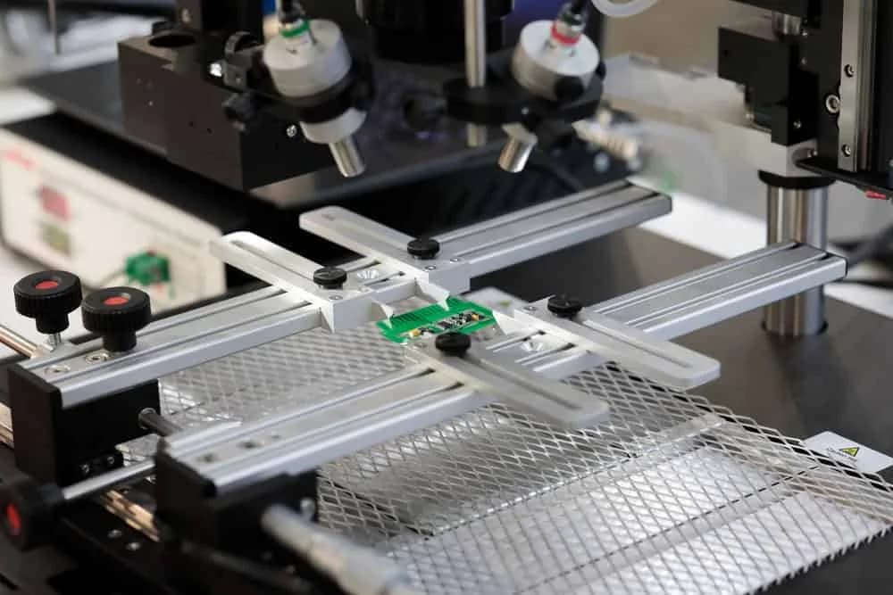
Quick-Turn Workflow
1
File Review and Quote Readiness
We check whether the package is actually releasable: fabrication data, stackup notes, bend intent, stiffener details, finish requirements, quantity.
2
Flex-Specific DFM Review
Engineering review focuses on bend radius, conductor placement in flex zones, coverlay openings, reinforcement strategy.
3
Quick-Turn Build Planning
The job is structured around prototype urgency, sourcing model, inspection scope, and whether the request is bare flex, assembled flex.
4
Release, Build, and Feedback Loop
We close open questions before release and capture lessons from the first run so ECOs, pilot builds, and repeat orders move faster with fewer surprises.
Quote Package Checklist
- ✓Gerber or ODB++ package with drill and outline data
- ✓Layer count, copper weight, and target stackup
- ✓Coverlay, adhesive, and stiffener requirements
- ✓Static versus dynamic bend notes and minimum bend expectations
- ✓Surface finish, quantity breaks, and target lead time
- ✓BOM, XY data, and assembly drawing when components are included

Related Manufacturing Paths
Flex Circuit Manufacturer
Use this when the priority is broader flex and rigid-flex capability rather than an explicitly quick-turn buying cycle.
PCB Assembly Prototype
A fit for assembled prototype boards that need fast DFM, sourcing support, and pilot-ready documentation.
Instant PCB Quote
Useful when the main bottleneck is quote readiness rather than the flex process itself.
Frequently Asked Questions
What does fast turn flex PCB mean on this page?
It means a quick-turn workflow for flexible printed circuits that combines speed with flex-specific engineering review. The goal is not only to ship faster, but to reduce avoidable delays caused by bend-area mistakes, incomplete stackup notes, stiffener ambiguity, and assembly-risk details that often surface after quotation.
What files are needed for a fast turn flex PCB quote?
The fastest quote package includes Gerber or ODB++ data, drill files, board outline, layer count, copper weight, coverlay requirements, stiffener details, surface finish, quantity, and any notes about static or dynamic bending. If components are included, add the BOM, XY placement file, and assembly drawing as well.
Can you support rigid-flex as well as standard flex circuits?
Yes. Standard single-sided or multilayer flex boards are usually the quickest to review, but rigid-flex builds can also be supported when the stackup, bend zones, and stiffener transitions are clearly documented from the start.
Why do fast turn flex PCB builds take longer than standard FR-4 in some cases?
Flex circuits carry extra process sensitivity around coverlay openings, adhesive systems, copper balance, bend radius, and reinforcement features. If those details are incomplete, the engineering clarification cycle can take longer than the fabrication itself.
Is this page only for prototypes?
No. The strongest fit is prototype and pilot work, but the same service also supports repeat low-volume production when customers want faster turns on revisions, ECO-driven reorders, or controlled ramp activity after validation.
How do you reduce first-pass risk on quick-turn flex projects?
We focus on the high-risk details early: bend-zone copper layout, stiffener registration, coverlay strategy, finish selection, panel handling, and whether the assembly process matches the flex construction. That prevents a supposedly fast job from turning into a respin or a re-quote.
Need a Fast Turn Flex PCB Quote?
Send the fabrication package, bend notes, and any assembly requirements up front. We will review the build for quote readiness and flex-specific manufacturing risk before it turns into a schedule problem.

Backed by our Shenzhen SMT factory
26 placement machines · 11 SMT lines
4 nitrogen reflow ovens
100% 3D SPI & AOI inspection
Per-board MES traceability
01005 & PoP in stable production