A single cold solder joint caused a $250K medical device recall last quarter. Here's how to identify, troubleshoot, and prevent the most common soldering...
The $250K Recall Case
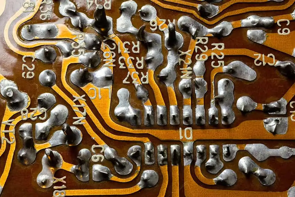
A Class II medical device manufacturer recalled 1,200 units last quarter due to intermittent signal loss. Root cause analysis revealed cold solder joints on 38% of returned units—all at QFN package connections with 0.4mm pitch. The failed joints showed characteristic dull, grainy surfaces when inspected under 10X magnification.
What Exactly Is a Cold Solder Joint?
A cold joint occurs when solder fails to properly wet the surfaces due to insufficient heat transfer. Unlike proper joints that exhibit shiny, concave fillets, cold joints appear:
- Dull/gray surface finish (vs. shiny)
- Grainy/crystalline structure (vs. smooth)
- Poor wetting angles (>90°)
- Visible cracks or voids
IPC-A-610 Class 2/3 explicitly rejects these defects under section 5.2.2 for through-hole and 5.3.2 for SMT joints.
Root Causes and Prevention
1. Insufficient Thermal Mass Management
Problem: Large ground planes act as heat sinks, preventing proper reflow. In our case study, the 4-layer board had 2oz copper pours under QFNs.
Solution:
- Use thermal reliefs in pads (IPC-7351 land pattern standards)
- Preheat boards to 150°C before soldering
- Increase soldering iron temperature to 350°C for hand rework
2. Contaminated Surfaces
Problem: Oxidized or contaminated pads prevent proper wetting. XRF analysis found sulfur contamination from improper storage.
Solution:
- Clean with isopropyl alcohol (IPA) before soldering
- Use no-clean flux with ≥0.5% activity level (IPC-J-STD-004 Type ROL0)
- Implement nitrogen reflow when oxidation risk is high
3. Incorrect Process Parameters
| Parameter | Cold Joint Risk | Optimal Range |
|---|---|---|
| Reflow Peak Temp | Too Low: <230°C | 235-245°C (SnPb) / 245-255°C (SAC305) |
| Time Above Liquidus | Too Short: <30s | 60-90 seconds |
| Cooling Rate | Too Fast: >4°C/s | 1-3°C/s |
Common Mistakes Engineers Make
- Assuming all components heat equally - Large BGAs and small passives need different profiles
- Neglecting pad finish effects - OSP has shorter shelf life than ENIG (6mo vs 12mo)
- Overlooking board warp - >0.75% warp causes non-contact during reflow (IPC-6012)
- Using expired solder paste - SAC305 paste loses activity after 6 months unopened
- Skipping pre-production trials - Always run 5-10 test boards before full batch
Prevention Checklist
- Verify reflow profile matches paste datasheet (thermocouple test)
- Implement first-article inspection with 10X magnification
- Store boards in nitrogen cabinets if ENIG finish >6 months old
- Use thermal simulation for boards with >40% copper density
- Specify IPC-A-610 Class 3 workmanship standards in contracts
- Require solderability testing per IPC/J-STD-002 for all components
- Train operators on visual inspection criteria (include defect samples)
FAQ
Q: Can cold joints be reworked?
A: Yes—fully remove old solder, clean with IPA, apply fresh flux, and reflow at proper temperature. Never simply "reheat" existing joints.
Q: How do X-ray inspections help?
A: X-ray detects voids >25% of joint volume (IPC-7095 standard), but cannot identify grain structure issues.
Q: Does lead-free solder increase cold joint risk?
A: Yes—SAC305 requires 20-30°C higher temps than SnPb. Always adjust profiles accordingly.
Q: What's the most overlooked cause in automated lines?
A: Conveyor vibration during cooling phase, which can fracture solidifying joints.
Q: How to test for intermittent cold joints?
A: Use 4-wire resistance measurement during thermal cycling (-40°C to +125°C).
Need Help with Your PCB Design?
Check out our free calculators and tools for electronics engineers.
Browse PCB Tools