About Capacitor Symbol, If you’re using any electronic device now, you’re likely using a capacitor without knowing. This critical component is useful as far as the storage of charge is concerned.
It’s made of two parallel plates separated by an insulating material or air.
But how do you identify a capacitor from a group of components? And how do you determine its polarity and other vital features?
This is where capacitor symbols come in. Since we have many different capacitor types, we use unique symbols to represent them.
For more about capacitor symbols, keep reading.
Table of Contents
- What Is A Capacitor?
- Capacitor Unit
- Capacitor Symbols
- Capacitor Markings
- Determining Capacitor Polarity
- Measuring Capacitance
- FAQ
- Conclusion
What Is A Capacitor?
This is an electronic component that stores charge in a circuit. Generally, it consists of two parallel plates with an insulating material or air between them.
We categorize capacitors into polarized and non-polarized capacitors. Interestingly, polarized capacitors come with definite anode and cathode.
Therefore, you can only connect them to the right terminals of your DC power supply.
However, a non-polarized capacitor doesn’t have an anode or cathode. Therefore, you can connect them in any direction. For this reason, it finds application in AC power systems.
Capacitor Unit
We refer to the ability of your capacitor to store charge as capacitance. We measure the capacitance in Farads, which we symbolize with F.
Generally, A farad is when one coulomb of charge changes the potential difference between the capacitor plates by one volt.
Surprisingly, we only have a positive capacitance. Therefore, we can represent charge in a capacitor by the formula below:
Q=CV,
Where: Q is the charge in Coulomb, C is the capacitance, and V is the voltage across the capacitor plates.
Remember, in circuits, you can connect your capacitor in parallel or series.
Capacitor Symbols
As we mentioned, a capacitor is an electronic component with two parallel plates and insulating materials between them. However, our symbol representing a capacitor varies with the type in question.
For example, although polarized and non-polarized have parallel plates, we represent them uniquely to capture their differences.
Therefore, check out the different capacitor types and their symbols below:
Electrolytic Capacitor
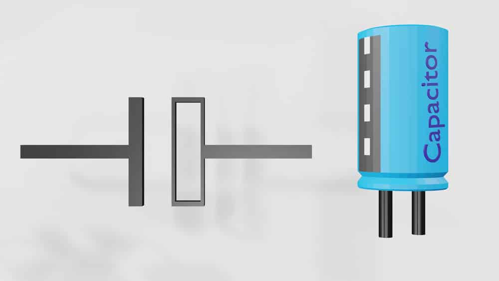
(An electrolytic capacitor symbol)
These are polarized components with anode plates having a metal. Moreover, it has a cathode that is made of a liquid electrolyte. The most common metal plates you’ll find are aluminum and tantalum.
Therefore, the metals undergo anodization to create an insulating oxide layer. The metal oxide will function as the capacitor’s dielectric.
Moreover, these capacitors offer a high capacitance than non-polarized options. Unfortunately, they present a high explosion risk and low tolerance.
Ceramic Capacitor
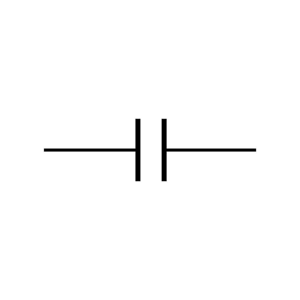
(Ceramic capacitor symbol)
This is a fixed-value capacitor with ceramic material functioning as the dielectric. They usually come with at least two ceramic layers and a metal layer as electrodes. Surprisingly, ceramic offers a cheaper and more compact design.
Generally, ceramic capacitors find applications in high-frequency applications. Therefore, expect them to offer you a low capacitance.
Polarized Capacitor
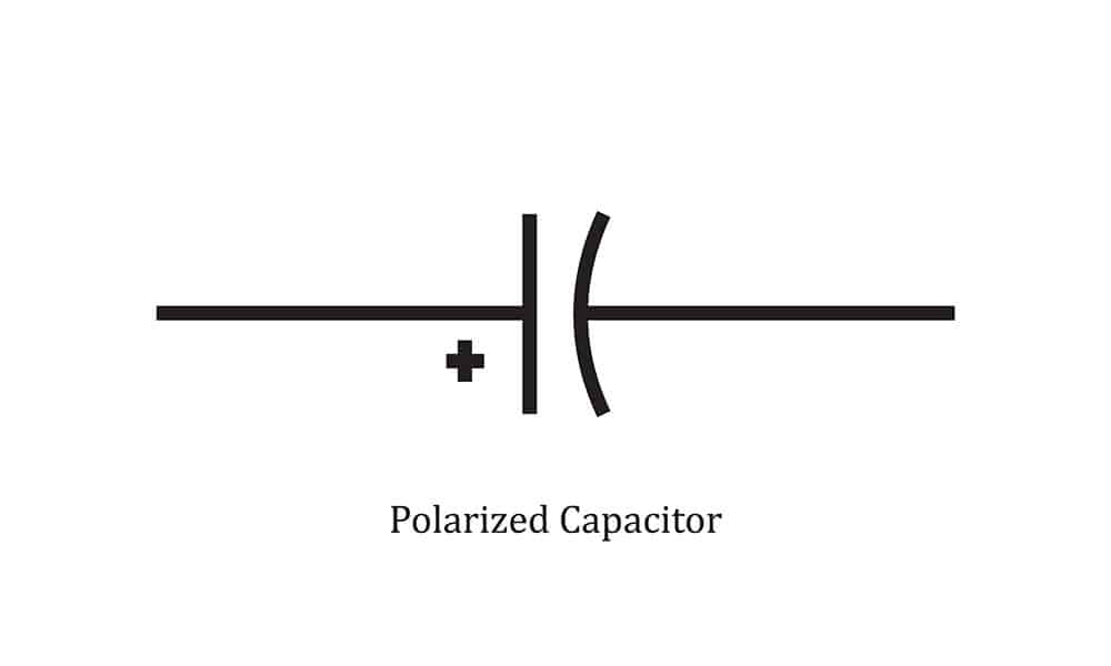
(A polarized capacitor symbol)
A polarized capacitor has a definite anode and cathode. Therefore, you can only connect their anode and cathode to your power supply’s positive and negative terminals. Also, if, by any chance, you connect them in reverse, they might get damaged.
Surprisingly, these capacitors can only work with DC power and not varying AC power. The electrolytic capacitor we looked at above is just a polarized capacitor.
Generally, these capacitors offer high capacitance. Moreover, you can use them in low-frequency applications.
Non-polarized Capacitor
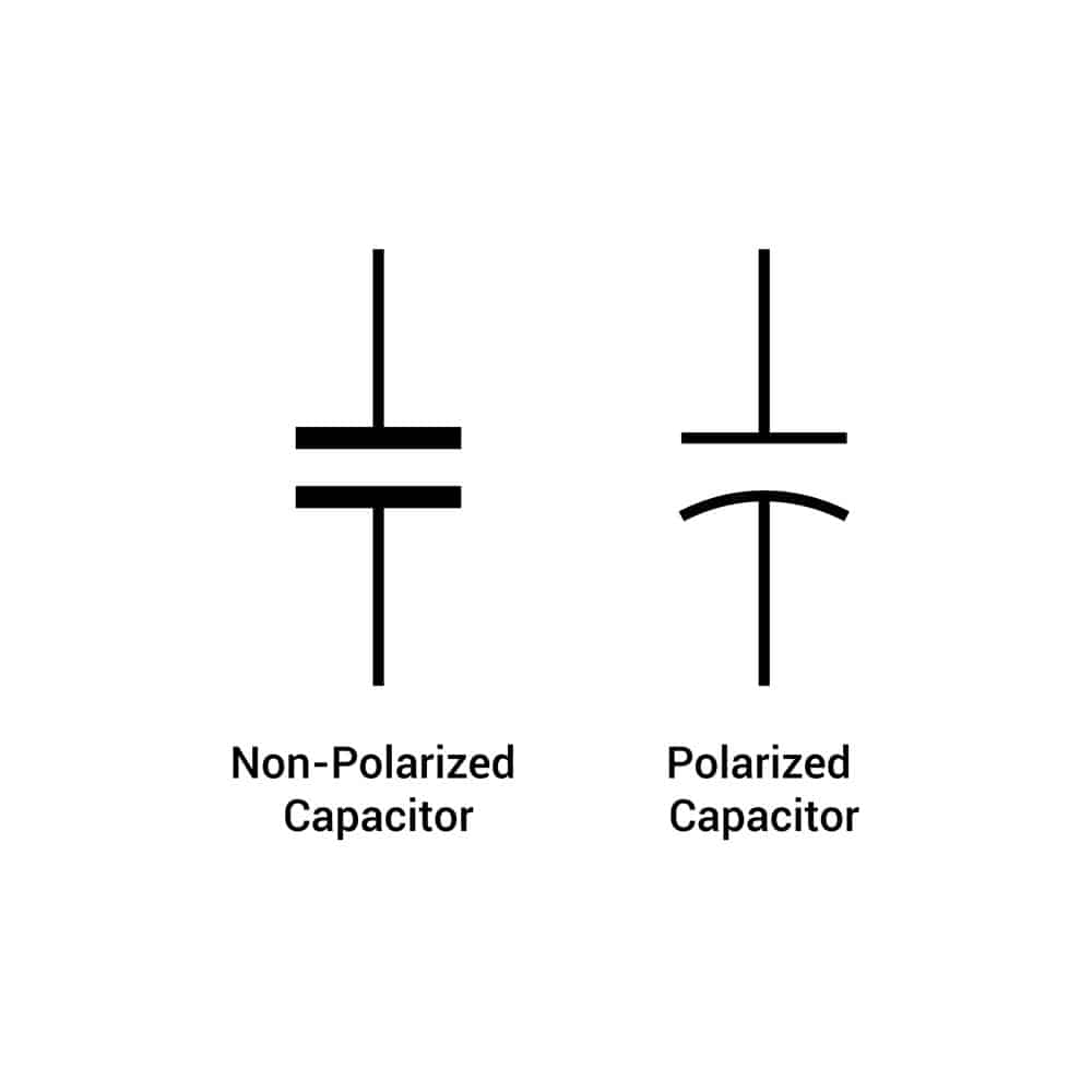
(Photo of polarized and non-polarized capacitor)
This capacitor is just the opposite of a polarized capacitor. These capacitors are designed without positive or negative poles.
Therefore, you can connect them in your circuit without considering the current direction. Moreover, they work well with AC power.
An excellent example of this capacitor is the ceramic capacitor. Generally, these capacitors offer low capacitance, which you can use in high-frequency applications.
Fixed Capacitor
These capacitors offer a fixed capacitance. Therefore, the distances between the parallel plates are fixed. Consequently, you can’t change or vary their capacitance value.
Good examples of fixed capacitors include compact electrolytic and ceramic capacitors.
Variable Capacitor
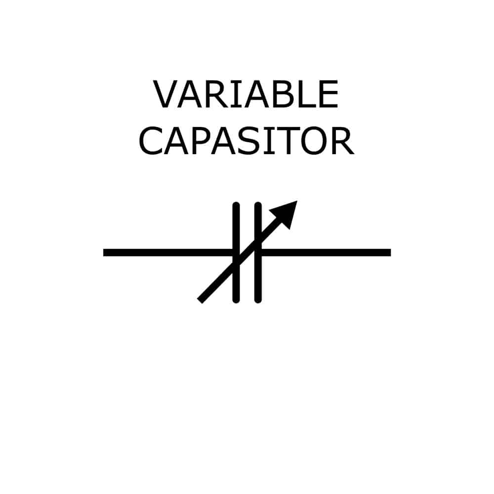
(A variable capacitor symbol)
Unlike a fixed capacitor offering a constant capacitance, a variable capacitance will provide varying capacitance depending on your requirement.
Therefore, you can use these capacitors in AC circuits that require high power, low loss, and high-frequency properties. Typical applications include antenna and radio tuning.
Trimmer Capacitor
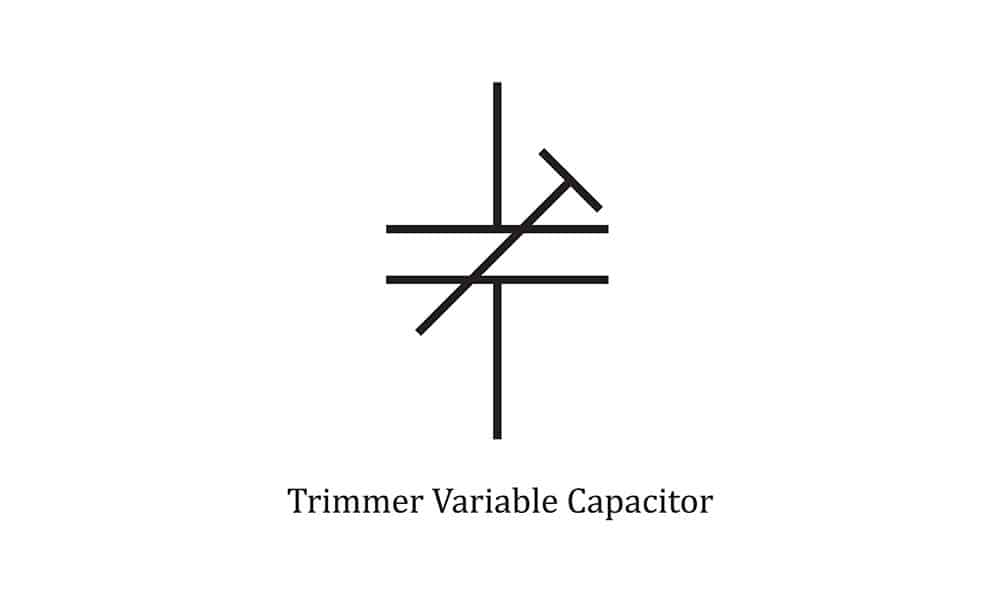
(A trimmer capacitor symbol)
This variable capacitor type employs trimming the capacitor’s dielectric medium to adjust capacitance. They find application in calibrating the oscillator frequency values and latencies.
Capacitor Markings
Capacitors come with different markings for identification purposes. Therefore, let’s check them out below:
Color Code
Different capacitor types come with unique color schemes. However, this was common in older components and not the new ones.
Tolerance Code
Every capacitor has a tolerance code representing the voltage it can withstand before getting damaged. Check the codes in the table below:
| Letter on Capacitor | Capacitor Tolerance |
| B | +- 0.1% |
| C | +- 0.25% |
| D | +- 0.5% |
| F | +- 1% |
| G | +- 2% |
| J | +- 5% |
| K | +- 10% |
| M | +- 20% |
| Z | + 80%, – 20% |
Temperature Coefficient Code
Most capacitors have temperature coefficient markings. Moreover, these markings are common in ceramic and film capacitors and undergo standardization by Electronics Industries Alliance.
Working Voltage Codes
This is the critical parameter of any component. Therefore, it defines the voltage that your capacitor can support. However, you might come across smaller capacitors that make writing a full voltage code challenging.
Therefore, manufacturers will only write a single character for the voltage value on the component.
Number Codes
Capacitors come with numbers on their body to represent their electrical properties. Large capacitors, like the electrolytic types, will have the actual capacitor. Therefore, this could be something like 120 µF.
Determining Capacitor Polarity
You can determine the capacitor polarity in two ways:
- First, all polarized capacitors are designed with polarity symbols. Therefore, you can determine the polarity just by visualization.
- Moreover, you can determine the polarity of your component by measuring it using a multimeter. Therefore, we recommend this approach if you aren’t sure of the polarity identifying features.
Measuring Capacitance
You only need a capacitor and a digital multimeter to measure the capacitance. Check out the below steps:
- First, ensure your multimeter’s black and red leads are in the correct plugs.
- Secondly, set the dial on the multimeter for the arrow to point to the capacitor symbol.
- Next, turn off your circuit power and discharge the capacitor.
- Remove the capacitor from your circuit and place its terminals on each multimeter lead. The value that you see on display is capacitance.
FAQ
Are all capacitors the same?
No! Capacitors vary in composition, design, and functionality. For example, a polarized capacitor has an anode and cathode and finds application in low-frequency applications.
However, non-polarized options have no anode or cathode and find applications in high-frequency applications.
Does it matter how you connect your capacitor?
It depends on the type of capacitor you’re using. With a polarized capacitor, you should carefully match its terminal polarities to the power source. However, you can connect a non-polarized capacitor without observing polarities.
What if you connect your polarized capacitor in reverse?
As mentioned, a polarized capacitor only works when its terminal polarity matches the power source. Therefore, the anode should go to the power source’s positive.
Surprisingly, doing otherwise might damage the capacitor or even cause it to explode.
Conclusion
A capacitor consists of two parallel plates with an insulating material in between. Surprisingly, we have different capacitor types, each with its symbol and markings.
The symbols and markings define the type and capacity of the capacitor. However, measuring your component with a multimeter is the best way to determine the capacitance.