What is a Gerber file? In PCB manufacturing, Gerber files are the software sketches that companies use to communicate information about the composition of circuit boards.
Before the invention of Gerber files, PCB manufacturers had no standard guidelines to follow when producing circuit boards.
Early layouts that envisioned the PCB specifications followed diversified content.
Graphic, descriptive, textual, bitmap, and vector formats did an excellent job of describing and representing the final project.
As a result, inaccuracies with measurements, dimensions, positioning, and other factors often occur.
It caused a lot of confusion and miscommunication between customers and production companies.
When the Gerber format got introduced, it brought universal compatibility between manufacturers and PCB designers.
Today, Gerber is a cornerstone of the PCB industry, especially regarding fabrication data.
Table of Contents
- What Is a Gerber File?
- Gerber File Formats
- Uses of Gerber Files in Manufacturing
- How Do You Generate Gerber Files in a PCB Design
- How to Convert a Gerber File
- FAQs
- Conclusion
What Is a Gerber File?
It’s an open ASCII vector format file that carries data on every physical board layer of your PCB design. The Gerber file represents circuit board components by a flash or draws code.
Vector coordinates define parts like copper traces, solder masks, pads, vias, and silkscreen images. PCB manufacturers then use these files to translate your design details into the PCB’s specified physical properties.
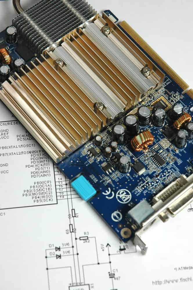
PCB with electronic chips
Gerber files are usually generated by the PCB design software that you’re using. However, the process varies with each computer-aided design (CAD) tool.
Most modern Gerber files follow the RS-274X Gerber format, which succeeded the older versions like the RS-274-D Gerber standard.
Therefore, Gerber data doesn’t need a specific identifying file name in text format. Instead, it’s often given a common extension name, like .gbr or .gb.

Engineer working on CAD software
Gerber File Formats
Gerber file formats have changed, especially regarding their data and structures.
Despite these changes, they all work towards the same goal: creating stencils for fabrication and reproducing the board. Here are the three basic categories of Gerber file formats:
RS-274-D Format
It was the earliest format of Gerber files. They only consisted of the draw, flash commands, and XY coordinates locations. Back then, PCB designers had to assign aperture codes manually during the file creation process.
Later, the configuration framework containing the aperture data would get extracted into a separate file.
Consequently, this forced designers to assign the correct codes diligently. Failure to do so led to inaccurate Gerber files. Therefore, the RS-274-D format negatively affected the PCB manufacturing process.
RS-274-X Format
Do you create Gerber files using your CAD system for PCB manufacturing? There’s a good chance you’re using the RS-274-X format.
This version blends the four main aspects of Gerber data into one file. These aspects include XY coordinates, draw and flash commands, apertures, and configuration parameters.
The file extension defines each layer’s function. This format eliminates the chance for human input errors, thanks to its ability to assign apertures automatically.
Gerber X2 Format
Gerber X2 format is the latest version. It has extra data on details like object functions, file layer functions, and the position of traces.
This information is written inside the file. The intended result is to improve the Gerber format to make it more like a database (like ODB++).
However, Gerber X2 retains its ability to drive LDI systems and photoplotters.
Uses of Gerber Files in Manufacturing
PCB manufacturing technology has improved tremendously over the past decades.
Previously, companies used vector photoplotters to create some of the materials used in the manufacturing process, like tooling film.
In addition, a focused light conducted through an aperture was used to expose the film to create the flashes and draws for each pad and trace.
Technicians only had a small set of apertures to work with, which meant designers had to get creative.
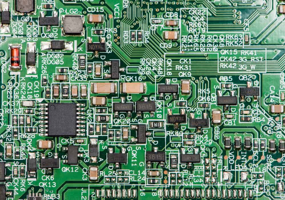
PCB with electronic components
In other words, they restricted their lines and flashes to the apertures they had available. On the other hand, modern manufacturing processes use a raster laser to open up the film.
This method is much faster than the old vector photoplotter. Subsequently, manufacturers have reduced the production time of circuit boards from several hours down to a matter of minutes.
So, what do Gerber files have to do with this? Well, you can trace their history back to the requirements of the original vector photoplotters.
They transmitted instructions to the plotter with files containing X/Y coordinates, flash or drawing commands, aperture positions, and minimal plotter configuration information.
Modern Gerber data has increased capability, functionality, extra configuration data, and aperture and macro definitions.
The laser plotters companies use today still have the same Gerber information.
The only difference is the aperture restrictions, once imposed by older vector plotters, no longer apply. Modern laser plotters convert the Gerber coordinates into something called a raster file.
This raster file has data commands that guide the laser plotter on what to create, where, and how to create it on the films.
For example, the aperture parameters control the size and thickness of the pads and traces. The flash and drawing determine whether the laser should create flashes, polygon fills, or lines.
Once this information gets conveyed, the laser sweeps across the film, exposing the image in real-time.
As PCB technology continues to advance, so do circuit board manufacturers continue to adopt new processes. Many have now switched to direct laser imaging.
As the name suggests, these lasers create PCB images directly onto the copper components, rendering the need for film obsolete.
New database formats, like net connectivity and board design data, come equipped with more intelligent data.
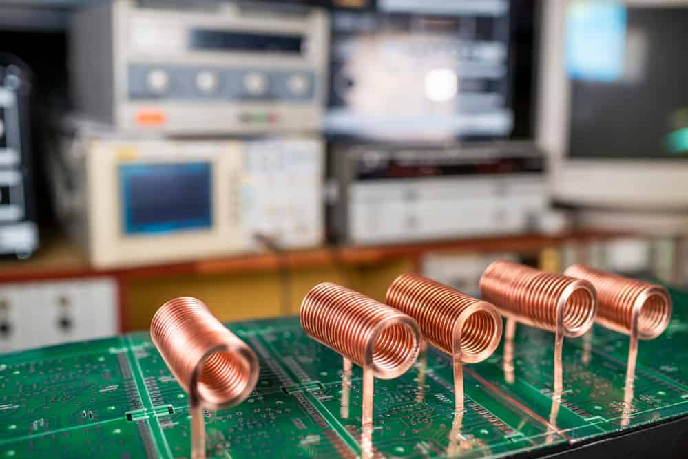
Copper wire
Now you can see why Gerber files are still crucial to the PCB manufacturing process.
How Do You Generate Gerber Files in a PCB Design
After completing your design (including final checks), you must generate the Gerber files for the PCB manufacturer.
How you choose to do this will vary, depending on the software you’re using for circuit board design.
Older tools involve many steps during setup and when you want to generate files.
Fortunately, most modern CAD packages have simplified this process. Instead of having multiple documents, the Gerber files you’ll need to produce a PCB will come as an individual file for every board layer.
Some companies may request extra Gerber layers for fabrication, assembly information, or board outlines. However, such requests are rare unless you want a custom design configuration.
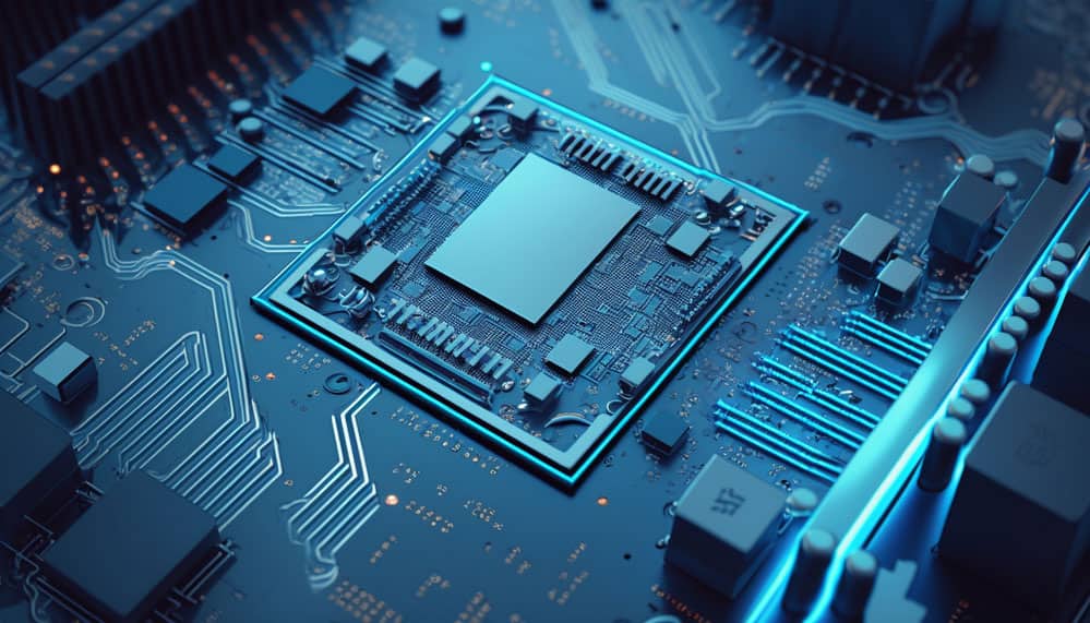
Circuit board futuristic concept
Finally, you’ll have to set up the Gerber file generator before you create the files. This step ensures that the standards, formats, and units get configured according to your and the manufacturer’s design standards.
How to Convert a Gerber File
If you want to convert a Gerber file, figure out its format first. Once you know the format, you can select the appropriate converter program.
It’s important to remember that different file formats aren’t interchangeable. You cannot, for example, convert a GIMP format brush file into a Gerber format file.
Apps like GerbView will help you convert files into PDF, DXF, SVG, and DWG formats.
An online Gerber viewer can also work if you want to save a Gerber file in PNG format. FlatCAM turns a Gerber file into G-Code. If no other converters work, then try Cenon.
FAQs
What Programs Create Gerber Files?
There are several design software used to make Gerber files. Examples include Eagle software, Altium Designer, and Kicad.
What Is the Purpose of a Gerber Files?
A Gerber file carries information about a PCB’s design and other specifications. In simple terms, it’s a blueprint for building PCBs.
What Format Are Gerber Files In?
Gerber files are in the ASCII vector format.
Can You Edit Gerber Files?
Yes. You can edit Gerber files using a text editor app.
Conclusion
If you’re a PCB designer, understanding Gerber files is a must. It includes the data, their formats, the information they carry, and the programs needed to convert them into different formats.
Much about PCB manufacturing has changed, but the role and importance of Gerber files remain the same.
They’re not about to get replaced anytime soon, so you may learn everything you can about them while you can.